
- Tue Jan 11, 2011 7:15 pm
#20
We were recently asked about our Gantry design from a backer of our project. He asked about the style of gantry and design process that we went through. We have heard some comments about how our machine seems to be more about form, rather than function. That couldn't be further from the truth. Form definitely followed the function of this design.
We wanted to put together a look at how the design progressed to where it is today... starting from 5 months ago. Since our project literally hinged on three parts: Table Structure (X-Axis), Gantry (Y-Axis) and our Z-Axis, we figured it would be great to look at the design as it developed in these key groups. Let's start this update with the Gantry (Y-Axis).
We often referred to ourselves as "Team Gantry". We knew from the start that we wanted to build a gantry style machine. Figuring out the critical blend rigidity and resilience has been a difficult task.
Take a look at the photos below.
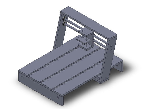
Photo 1: We started with a quick sketch of what we thought a gantry machine would look like. We knew in order to maximize surface area, we would need to make the gantry offset from the straight up and down line of the X-axis. This was also an important thing for center of mass. We wanted to maximize cutting area, AND have our center of mass be over the center of the bottom of the gantry.
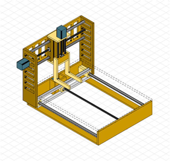
Photo 2: Our first refined design. This design was heavy duty. It was big, it was bulky. It was kind of cool and unique, the gantry actually tucked under the motor to minimize the machines' footprint. However through design we were unable to come up with an ideal solution to accommodate motors of varying size and lengths. This however was the start of our machines' final design.
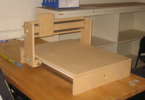
Photo 3: We made significant improvements over the designs we had, while addressing key concerns. The gantry was made a bit smaller than our previous design. It was still square and rather bulky, but at this point it was a working machine.
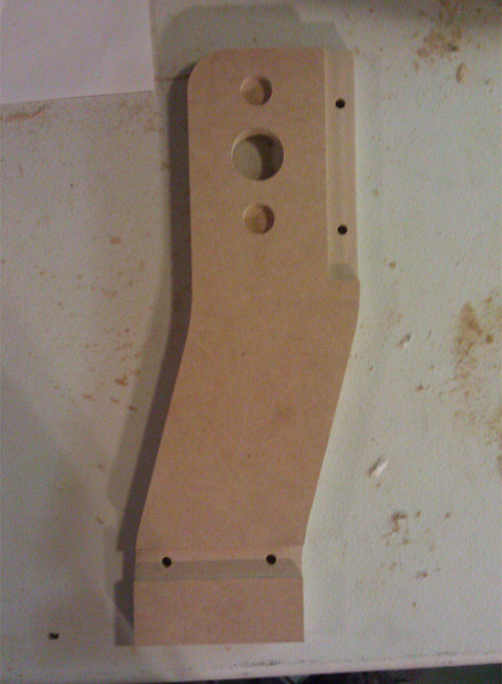
Photo 4: From there it was time to trim the fat. Our gantry arms were big, they were square, they were overkill. Using our new CNC's capabilities. We cut new gantry arms that had a smooth shape, while not affecting strength.
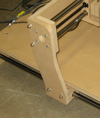
Photo 5: We also found quickly that we needed a new method of holding in the shafts, while maximizing the cutting area. Our improvements also include internal threaded nuts to prevent having to drill and tap MDF (which is not a very good thing to do), which will allow for a greater life expectancy.
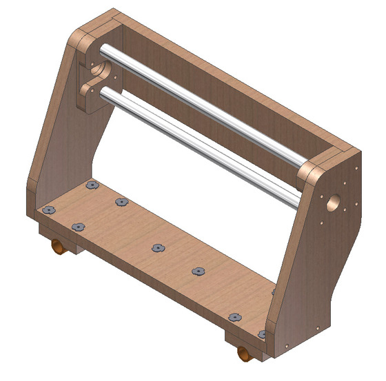
Photo 6: Where we are now. Several improvements were made between the last gantry design and the new one. You will notice the new shape on the gantry sides, they were made shorter and wider. The new shaft supports maximize cutting area, adjustability, and hold our bearings to pre-tension the shafts. And the bearing blocks on the bottom are fully upgradable to aluminum bearing blocks.
Form definitely follows function.
We wanted to put together a look at how the design progressed to where it is today... starting from 5 months ago. Since our project literally hinged on three parts: Table Structure (X-Axis), Gantry (Y-Axis) and our Z-Axis, we figured it would be great to look at the design as it developed in these key groups. Let's start this update with the Gantry (Y-Axis).
We often referred to ourselves as "Team Gantry". We knew from the start that we wanted to build a gantry style machine. Figuring out the critical blend rigidity and resilience has been a difficult task.
Take a look at the photos below.
Photo 1: We started with a quick sketch of what we thought a gantry machine would look like. We knew in order to maximize surface area, we would need to make the gantry offset from the straight up and down line of the X-axis. This was also an important thing for center of mass. We wanted to maximize cutting area, AND have our center of mass be over the center of the bottom of the gantry.
Photo 2: Our first refined design. This design was heavy duty. It was big, it was bulky. It was kind of cool and unique, the gantry actually tucked under the motor to minimize the machines' footprint. However through design we were unable to come up with an ideal solution to accommodate motors of varying size and lengths. This however was the start of our machines' final design.
Photo 3: We made significant improvements over the designs we had, while addressing key concerns. The gantry was made a bit smaller than our previous design. It was still square and rather bulky, but at this point it was a working machine.
Photo 4: From there it was time to trim the fat. Our gantry arms were big, they were square, they were overkill. Using our new CNC's capabilities. We cut new gantry arms that had a smooth shape, while not affecting strength.
Photo 5: We also found quickly that we needed a new method of holding in the shafts, while maximizing the cutting area. Our improvements also include internal threaded nuts to prevent having to drill and tap MDF (which is not a very good thing to do), which will allow for a greater life expectancy.
Photo 6: Where we are now. Several improvements were made between the last gantry design and the new one. You will notice the new shape on the gantry sides, they were made shorter and wider. The new shaft supports maximize cutting area, adjustability, and hold our bearings to pre-tension the shafts. And the bearing blocks on the bottom are fully upgradable to aluminum bearing blocks.
Form definitely follows function.
 - By Sam_CNC